Overview
This lab is a continuation of Lab 07.
After completing your final electrical test (all the THT components mounted) with a course staff, you can attempt to upload the board’s firmware.
You’ll also receive 2 speakers from the course staff.
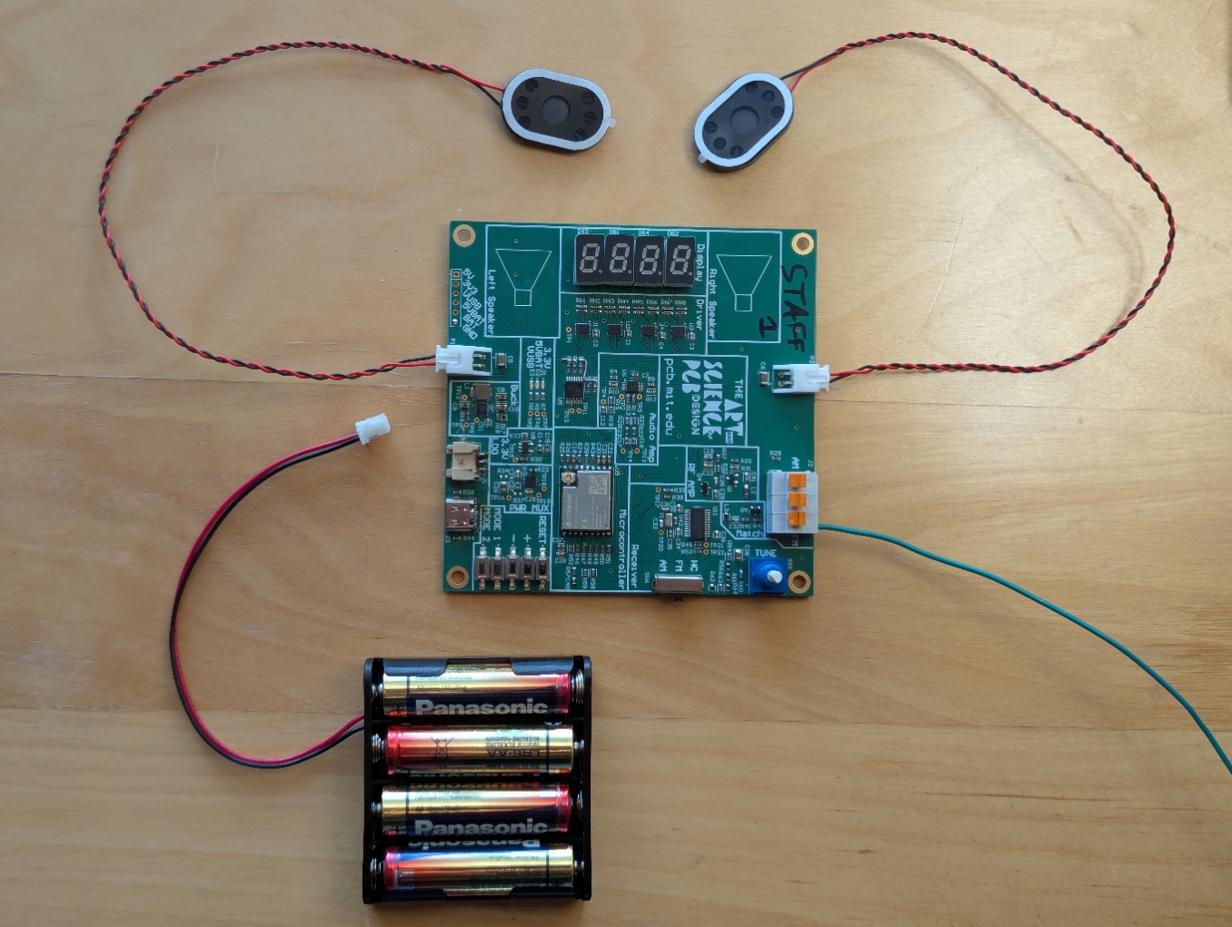
Final Hardware Setup
Cut an approximately 75 cm long wire and strip one about 1 cm of it at one end - this will be your FM antenna.
Attach your speaker(s) and wire antenna to the FM input of the terminal block.
Firmware
Setup Arduino IDE
If you don’t already have Arduino IDE installed, download and install it from here
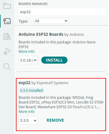
Arduino does not support ESP32 out of the box. Open the Boards Manager (on the left toolbar) and install the esp32 package by Espressif Systems.
Download the repo
The FM radio board can be programmed with Arduino over USB. The firmware script is necessary to get the radio and display functionality operating.
Flash the code
Finally, you should be able to flash the code. Open the .ino file in Arduino. Under Tools, set the Board to ESP32C3 Dev Module and enable USB CDC On Boot.
Now, plug in your board to your computer using a USB cable(make sure that you’ve done your electrical tests first). You should have port pop up under Tools that you can select, the press Sketch->Upload. If this doesn’t work, let a staff member know and we will help you out, or try out some of the Debugging steps below.
Debugging
If you do not see a new port when you plug in your board, it is most likely an issue with soldering the USB connector. Double check that none of the pins are shorted, and that they are all look to be connected. Also, make sure the the USB pins on the ESP32 (IO18 and IO19) seem to be properly soldered down.
If you do see the port, but it keeps disconnecting and reconnecting, we have a fix for this (probably). You can try fixing this by installing esptool. Then, with the board plugged in run esptool.py chip_id (or likely just esptool chip_id on Windows) in the terminal. It might take a couple of attempts to run this at a time when the port is connected. Without unplugging the board, try programming again from Arduino.
Functionality
With the firmware properly uploaded, the board should display the frequency it is tuned at, which is adjustable via the potentiometer. The volume can be adjusted using the + and - buttons. Finally, you can switch between the AM/FM modes by using the SP3T switch then pressing the RESET button.
Optional Audio Amp
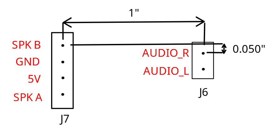
If you want to customize your board, we added some headers so that you can put in your own custom audio amplifier instead of using the one based around the AD8592 op amp. The relative dimensions of these headers are included below. You can solder your own 0.1” headers into J7 and J6 to easily access these pins.
| Pin | Description |
|---|---|
| Audio_R | Direction connection to the audio output of the receiver chip |
| Audio_L | Direction connection to the audio output of the receiver chip |
| SPK B | Connection to P2B through C6 |
| SPK A | Connection to P2A through C5 |
| GND | Ground |
| 5V | 5 Volts |
If you do implement and connect an external audio amplifier, make sure to disconnect the op-amp based amplifier so that it doesn’t interfere. To do this, you can depopulate R4, R10, R9, R12, R22, and R23. Also, if you continue to use the speakers the small Same Sky CMS-30204-18L250 speakers, make sure to stay within their power limits.