Introduction
Now that your FM radio project board has been fully designed from schematic to layout, it’s time to assemble it into a full device.
In order to ease logistics for a 4-week long IAP class, the course staff has designed and fabricated a near-exact replica (electrically) of the FM radio board you created. You will get your own copy of this board as well as the required components to assemble it.
Safety
You’ll be soldering a bit in this lab, first with solder paste and hot-air reflow, then with a solder wire and soldering irons of soldering irons. Please wear safety glasses (grab a pair from the stations inside the lab or from EDS) and keep in mind:
- Hot things: The hot-air reflow stations heat the boards up via a pre-heater on below where the board sits (think of it like a stovetop) and via blowing hot air on them with a hot-air reflow gun. Both the pre-heater and hot-air gun can badly burn you if you touch their metal parts. Additionally, keep an eye on where you’re pointing your hot-air reflow gun, and make that isn’t towards you or other students. Finally, when you’re done reflowing your board and you want to pick it up for testing or to celebrate, DON’T! Your board will still be VERY HOT from the reflow soldering and can easily burn you. Instead, turn off the pre-heater and hot-air reflow gun and wait for your board to cool down before removing it.
- Heavy metals: While the solder paste we’re initially giving you is lead-free, we might run out and have to use solder paste with lead. Since solder paste is filled with microscopic metal solder balls, it get all over your hands without you noticing. Since we don’t want you ingesting it (whether leaded or lead-free), be sure to wash your hands after handling solder paste. We’ll also be giving you gloves to wear while pasting your boards - feel free to keep them on or grab new ones during population if you’d like.
- Carcinogenic Solder fumes are caused by the flux within the solder vaporizing. It is probably carcinogenic and definitely not something you should breath in. Be sure to use the fume extractor fans to ventilate your work area.
- Sharp things: The tweezers are sharp, don’t stab yourself with them. Be gentle with them too - it doesn’t take a ton of force to keep a part in your tweezers, and you’ll send it flying if you squeeze too hard. Additionally, be sure to clean off your tweezers after use so that other students may use them.
- Tiny things: Solder flux has a tendency to fling out of hot solder and all the miniscule chip passive components are able to fly fast and far if handled improperly. Grab a set of safety glasses from EDS keep any stray flying bits out of your eyes.
SMT Reflow
Preparation
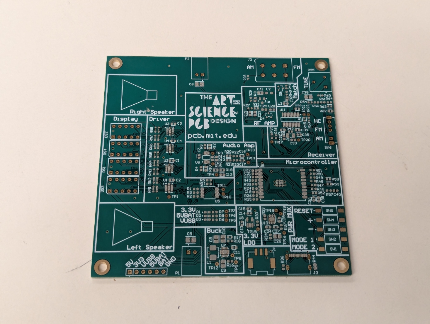
Begin by retrieving a blank staff-design FM radio PCB from the components table. Take a sharpie and write your kerb at the top-left corner on the front of the PCB. It’s now your very own PCB!
Grab a pair of tweezers from the tables where all the components are located. Please, please, please, retain the paper/plastic packaging and the plastic cover that protects the tweezer’s tips. Additionally be very careful not to drop the tweezers or bend the tips. Once the lab section concludes, clean off the tweezers and place them back in their packaging. The students in other lab sections thank you in advance.
Find a flat table area where you can work. The SMT components are small and hard to place, so it’s good to have a static, level workspace to populate it on.
Stenciling
The first step of reflow soldering is stenciling your board to add solder paste to it. You will only be stenciling components with small SMT pads on your board. Therefore, you will not be stenciling/placing components such as:
- Through-hole components
- Pushbuttons, which melt easily if not reflowed properly
- Zero-ohm resistor
R66, which is a do-not-place (DNP) jumper.
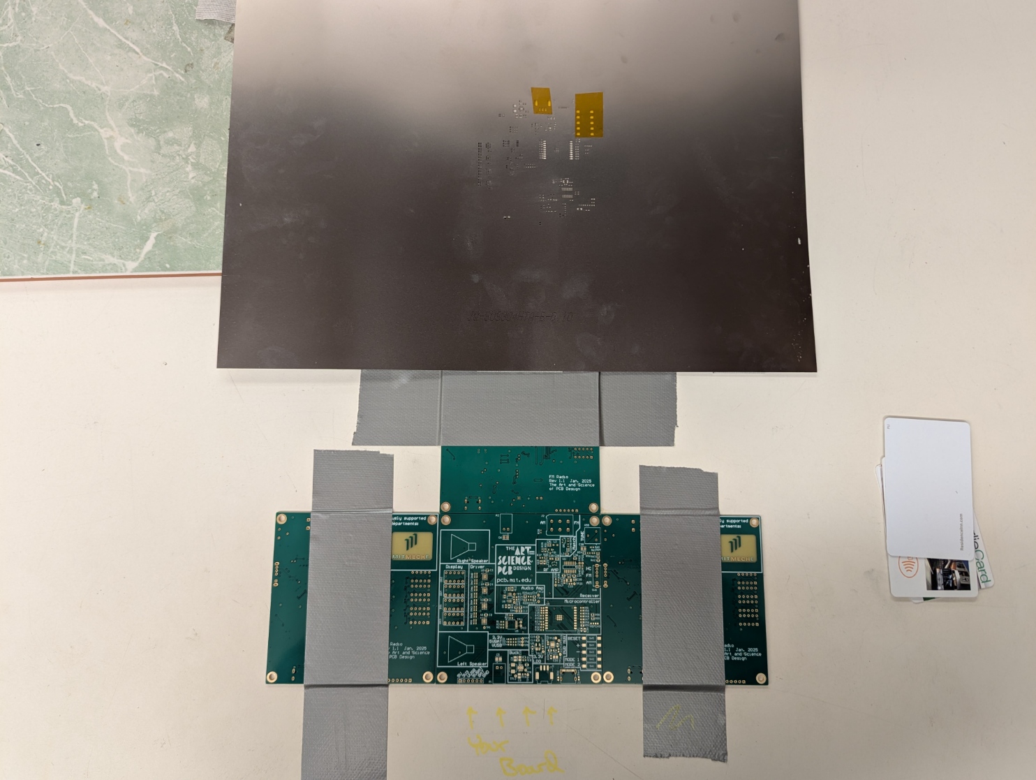
We’ve set up some stenciling stations around lab with a setup that looks about like this. Here’s a video that shows you how to do the stenciling, it’s of a different board but the process is exactly the same:
We’ve also put a little piece of kapton over some parts of the stencil that we don’t want to put solder paste through. Be careful to not peel these off with your spudger!
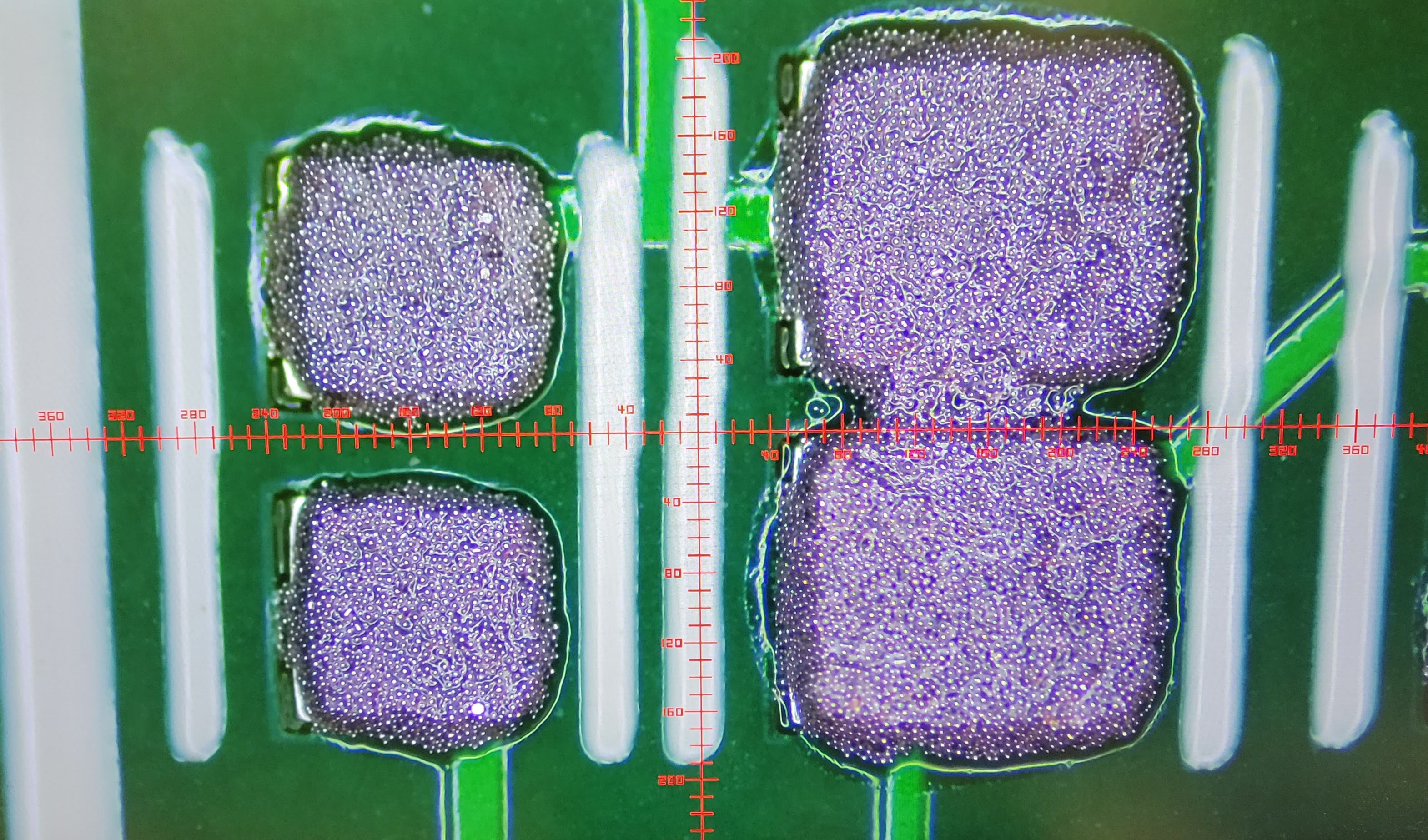
Feel free to have a quick look at your board under the microscope once you’ve got paste on. You can see the little solder balls under there, and how crisp your stenciling job was.

To further illustrate this, you will first begin by placing your board in the stenciling jig.
You’ll then follow the pasting process described in the video. After carefully lifting up the solder stencil and removing your board, you should end up with paste covering all of your SMT pads.
SMT Population
Once you’ve finished stenciling your board (yay!) we’ll go ahead and start populating the board.
Use the following FM radio board staff design BOM to populate your board.
FM Radio Board (Staff Design) BOM
Keep in mind the following notes as you populate your board:
- Do NOT mix components up. They are difficult to differentiate, so it is a good idea to grab them one by one.
- Do NOT place
R66. This is an example of a DNP component, which are added to help with debugging. - Do NOT place any through-hole (THT) components as you’ll need to solder them by hand after the SMT reflow
- Do NOT place the pushbuttons (
SW1throughSW5). Although these are SMT components, they easily melt if not reflowed properly, so you will hand solder them to the board instead. - Watch for the orientation of integrated circuits and diodes. In general, the dot on the IC denoting pin 1 should be oriented to match the dot denoting pin 1 on the footprint. For diodes, there is a dot or line on both the footprint and diode package that denote the cathode.
- For the ESP32 module (
U9), orient it such that the text on its shield is upside-down relative to the rest of the text on the board. There is a dot that aligns with pin 1, but it is difficult to see.
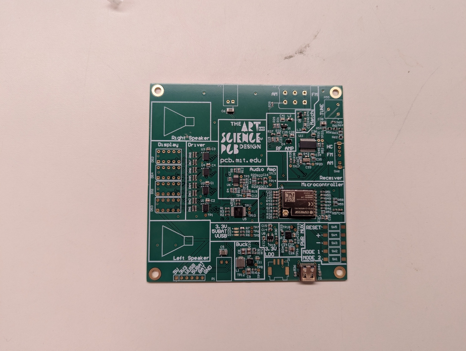
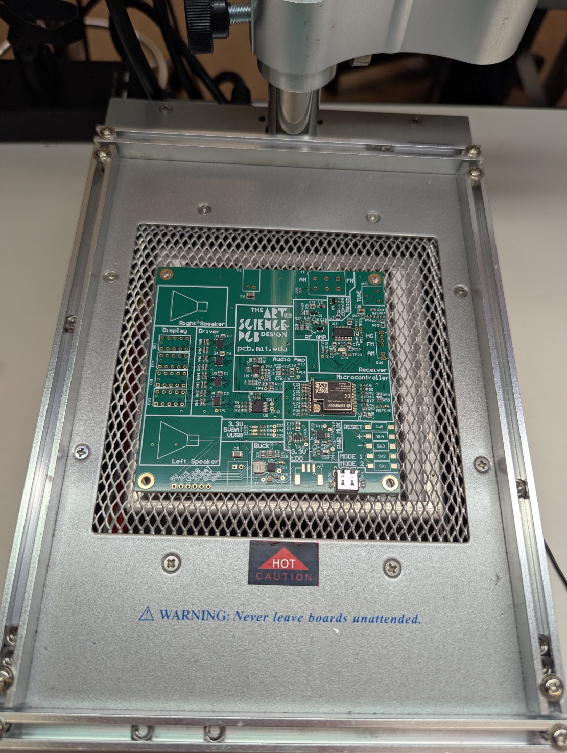
After the SMT population, your board should look similar to this:
Hot-Air Reflow
Bring your populated board to a reflow station at the far end of lab and carefully place your board on the pre-heater (NOTE: use caution as the pre-heater and reflow station may be HOT).
Once placed on the pre-heater, begin the process of reflow soldering:
- Set the airflow knob to zero - all the way to the left. This is to make sure we don’t accidentally blow away our parts!
- Turn the station on with the big black switch in the back.
- If it isn’t already on, enable the the Hot Air and Preheater switches on the front. If they’re off, they’ll say OFF. If they’re not, they’ll say H100, or whatever temperature they’re at.
- Go ahead and set the preheater to 150°C, and the hot air to 280°.
- Gently throw ya board on our little barbeque once it’s all up to temperature. Make sure the hot air gun is not pointing at the board just yet.
- Once it’s been a minute or two and the board is done preheating, go ahead and grab the reflow gun. Pick a spot to start, and hold the gun 3-4 inches away from the board, and move it around in small circles to evenly heat the part. You’ll see the solder paste change color as the goo holding the parts in evaporates off, leaving the solder balls behind. This means the paste’s heating up, keep going until you see it properly melt and reflow. The pins/pads should look silvery and shiny when the solder paste has properly reflowed.
- Keep moving around to the other parts of the board, soldering everything you’ve populated. This part’s super satisfying, so enjoy it 😎
- Once you’re done, turn the station off. Let everything cool down for a few minutes before taking the board off - we don’t want to bump the parts off while the solder’s still molten. Because that would be like, super sad. And we’re in this for happy vibes 💖
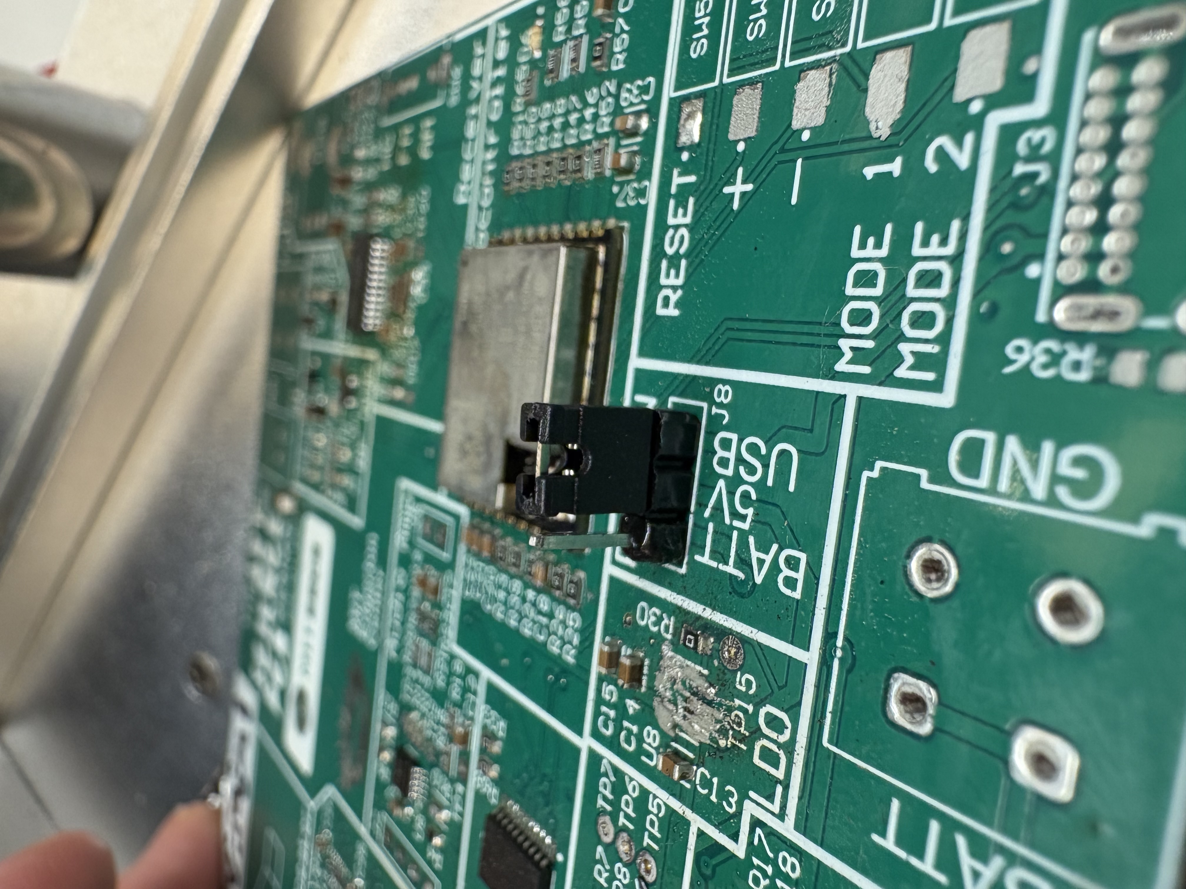
Hand-solder the PWR SW pins
Before we can proceed to do the electrical test, we need to hand-solder one component. Break off 3 pins from a 0.1” header strip, but keep the 3 pins together. Then solder this into J8. This will take the place of the power multiplexer that we implemented in lab. To switch between battery and USB power, you can use a jumper to alternatively connect 5V to BATT or USB.
Electrical Test
After your board has cooled off and you have visually inspected the solder joints on all of your components for the absence of any shorts, do a quick electrical test to check for any electrical shorts.
Use a multimeter and along the pin header row on the bottom left corner of your board, do a continuity test between GND and the other power pads (i.e., BAT, 5VBAT, VUSB, 3V3, and 5V). There should be no electrical continuity between these pads/nets. You might notice that when you check for a short to GND on VUSB and 5VBAT that their corresponding LEDs light up - that’s normal and expected!
If the visual inspection and multimeter test find zero shorts, we’ll supply power to the board to check that the power regulators work properly. To do this:
- Grab a benchtop power supply and set its voltage output to 5 V with a 0.5 A current limit.
- Connect the power supply to the
GNDandBATpins. If your power supply leads consist of alligator clips, using some stripped wires may help - Connect the PWR SW jumper between
5VandBATT. - Turn the power supply on and you should see the 3.3V and 5VBAT LEDs light up immediately. If this does not happen, immediately turn off the power supply.
- Connect the power supply to the
GNDandVUSBpins. - Connect the PWR SW jumper between
5VandUSB. - Turn the power supply on and you should see the 3.3V and VUSB LEDs light up immediately. If this does not happen, immediately turn off the power supply.
- Turn the power supply off when finished
Hand-Soldering
With all of the SMT components soldered down, it’s time to place the rest of the components, which we’ll do by hand using a soldering iron.
Through-Hole Components
The first component you need to solder-down by hand is the USB-C connector. First, make sure the connector is flat against the board and solder down the 4 mounting pins at the sides of the connector. Then solder the tiny pins that go into the board. These likely won’t poke through the board, so to solder these get a blob of solder on your iron and slowly run it along the pin holes. Some flux may help the solder flow into the holes.
After getting the USB-C connector down, solder the rest of the through-hole components! They’ll be located in large reels/bags, ask the course staff as to where to find them.
Don’t forget to also hand-solder your pushbutton switches (SW1 through SW5)!
Because the terminal blocks we intended to use for J1 and J2 went out of stock, we will be using ones that don’t exactly fit the footprint on the board. The terminal blocks we are using have only 2 pins instead of 4. Place them in the two pins closest to the board edge, and ensure that the side that the wires go in is facing out.
Electrical Test - Again
Once all of your through-hole components have been soldered down, do the electrical test you did after the SMT reflow once more.
Use a multimeter and along the pin header row on the bottom left corner of your board, do a continuity test between GND and the other power pads (i.e., BAT, 5VBAT, VUSB, 3V3, and 5V). There should be no electrical continuity between these pads/nets. You might notice that when you check for a short to GND on VUSB and 5VBAT that their corresponding LEDs light up - that’s normal and expected!
If the visual inspection and multimeter test find zero shorts, we’ll supply power to the board to check that the power regulators work properly. To do this:
- Grab a benchtop power supply and set its voltage output to 5 V with a 0.5 A current limit.
- Connect the power supply to the
GNDandBATpins. If your power supply leads consist of alligator clips, using some stripped wires may help - Connect the PWR SW jumper between
5VandBATT. - Turn the power supply on and you should see the 3.3V and 5VBAT LEDs light up immediately. If this does not happen, immediately turn off the power supply.
- Connect the power supply to the
GNDandVUSBpins. - Connect the PWR SW jumper between
5VandUSB. - Turn the power supply on and you should see the 3.3V and VUSB LEDs light up immediately. If this does not happen, immediately turn off the power supply.
- Turn the power supply off when finished
Stashing Your Board
If your board is unfinished by the time lab ends, make sure all of the components you grabbed have been placed onto the board, ensure your kerb is written on the board, and place your board on any workbench in the lab. Nobody should be touching your board between now and next lab.