Installing KiCAD
The first step is to Install KiCAD if you have not done so already. No licensing is required and it should work on all platforms.
Installing Templates and Plugins
We suggest that you use Winnie’s templates for this class. They change a few things that will make our lives easier, such as:
- Defaulting to 8.5” x 11” sheets rather than A4 (You may print out your schematics at some point, and this is handy)
- For some reason there’s no place for your name besides the comments by default
- Adding rules for fab houses, trace widths for controlled impedance nets
You don’t need to use this provided template, but you may want to manually set these things up yourself otherwise. Obviously, change the name on the template sheet if you use it. You can go to KiCAD and go to Drawing Sheet Editor. Open the template file (WS_Worksheet_Letter) and edit the name. Edit the sheet as you wish and then save.
Installation is fairly simple– Download the zip file and unzip it. Then in KiCAD, go to preferences -> edit paths and tell KiCAD where your downloaded folder is.
There’a also a few plugins that you might find handy. You can open KiCAD and open the “Plugin and Content Manager” (the bottom icon with the package image) and scroll through the various items. We enjoy using:
-
Interactive HTML BOM - lets us make things like this
-
KiBuzzard - it’s how we made the labels in this board
-
PCBWay Plug-in for KiCAD or Fabrication Toolkit - it makes manufacturing file data a simple click away.
Introduction
This lab is a super simple, super short lab! It’s basically just to get you familiar with the following in KiCAD.
- project structure
- schematic capture
- layout tools
- component libraries
We will be designing a very simple PCB from start to finish, not accounting for ANY parasitics, or following really any “good design principals.” Remember, this lab is JUST FOR YOUR FAMILIARITY with the software. This is by no means a “well designed PCB.”
The order you will do things in this lab is…
- select your components
- create a schematic
- create a layout of these components
- define a board shape
Overall Design
In this lab we’ll be designing a very simple board with an LED, a resistor, and a JST-XA header (here’s the datasheet in case the link is broken). Pretend you need a tiny PCB with an LED on it, maybe you’re making a flashlight. But none of the power electronics are actually on the board. You’ll use the JST header to send a voltage to the board (connect a power supply / battery), the resistor will limit the current, and the LED will shine.
How does an LED work?
Brief aside for those who don’t know, anyone who does know can skip this section. LEDs shine with a brightness proportional to the current flowing through them. Most LED circuits have what is called a “current limiting resistor” which limits the current from the power source to an appropriate level for the LED. If the resistor is not there, the LED would burn out immediately when hooked up to a voltage source.
LEDs also have a voltage drop across them when they are turned on. This voltage drop is NOT proportional to the current through the LED nor the applied voltage, however is specific to the LED and is based on the internal characteristics of the silicone. We can draw the following circuit diagram for the LED, resistor, and power connector.
If we look @ the datasheet for a typical LED we can see the values of the two parameters we care about, the forward voltage, and forward current per chip. In this case, the forward current needed for the LED to work is 20mA. Let’s call this $ I_{fw} $. When on, the LED will have a voltage drop between 1.7-2.6V, let’s call this $V_{drop}$.
Now let’s assume we’ll power the board with four AA batteries (if we’re making a flashlight), that’s a voltage of 6V if they’re in series. Let’s call this voltage $V_{in}$. The current can be calculated as follows. The value of the resistor is $R_{limit}$.
$I_{fw} = \frac{V_{in}-V_{drop}}{R_{limit}}$ (Ohm’s Law)
That means the voltage across the resistor at MAXIMUM will be 6V-1.7V which is 4.3V, so if we want 20mA of forward current, $R_{limit}$ must be 215 Ohms. Note that 20mA is extremely bright! For a flashlight this might be fine, but for an indicator LED for troubleshooting or such you might want 0.5 mA - 1 mA of current so you can still see the board.
Component Selection
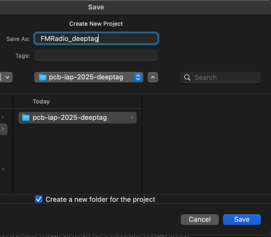
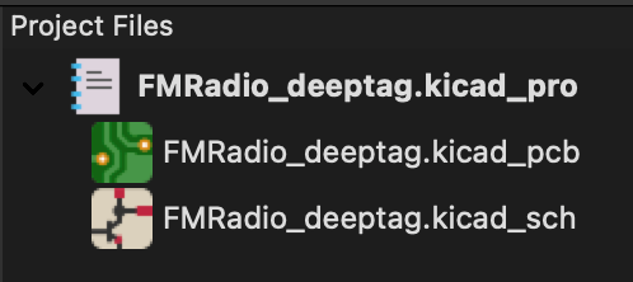
Create a new project by going to “File”–>”New Project from Template” if you’re using a template, or “File”–>”New Project” if you’re not. Name it “Lab 01_{your kerberos}”. For now you can save it wherever, but if you’re doing your project design for assignment 02, be sure to save it in a folder where Github will recognize it and back up your files. See more about Github installation here if you haven’t already, and be sure you have it working soon.
When designing PCBs, we need to remember that we work with REAL components. We need to be able to find these components, and purchase these components. Therefore PCB design is entirely design for manufacturing (DFM) where component selection based on what is available is critical.
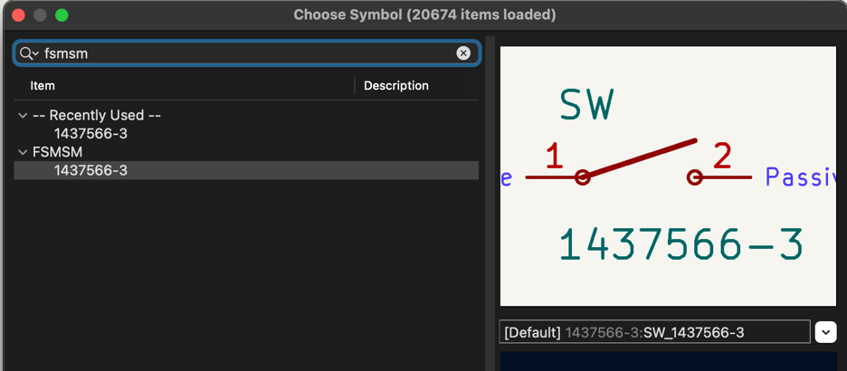
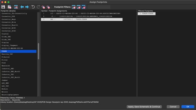
A Schematic defines the components of a PCB and how they are connected. It also tells KiCAD what components the design uses. KiCAD has many in-built parts libraries, some of which automatically pull the pin-out and the footprint of each part into your design. A Pinout is the definition of what to connect to what pin for a part, the footprint is the physical shape of the pads on the PCB. This mapping is absolutely crucial for components– if an incorrect pinout is defined, the footprint will be wrong and you’ll have to end up modifying the PCB. To ensure the pinout is correct, take a moment to look at the symbol and footprint. The pin that is described by the schematic should map to the correct pin on the footprint (as described on the datasheet). This is done with the pin numbers that are on the schematic and footprint. This is a very important concept, and we’d like you to take the time to understand what this means and how to check for a correct footprint.
KiCAD In-Built Component Library
KiCAD has a built-in library for very basic components and footprints (such as basic resistors and capacitors). It can be accessed from the “Add a symbol” icon (or hotkey A) on the right side of the screen.
In this case we know our design has a resistor. Let’s assume we’re ok with using a through-hole resistor FOR NOW instead of an SMD resistor (we’ll change it later).
Now we have to select the LED and the JST connector. Let’s put down a generic LED.
Once you put down the LED, we’re going to need to edit it so we remember what part it is. We suggest you do this right after putting down the part so you don’t forget and need to re-trace your search history. Select the part and double click it, or right click on it and click edit, or click on the part and press E. You’ll notice a lot of the fields are empty, so we’ll have to fill it in. Under datasheet let’s link the datasheet. What’s cool about this is if you save and exit the properties menu, you can now select the part and click D for the datasheet. It can be really handy!
We’ll also need to edit the footprint. Let’s double click the field to edit it. We’re going to need to look through the libraries to find the right footprint. Libraries can be a lot to deal with, and it’s good to be familiar with the different library names to pull from. Since we’re looking for a footprint for an LED, we’re going to search for “LED” on the very left column. Notice how there’s no implication for what size LED we’re looking for. This is because a library has the structure shown below, and we’re looking for the group, not the individual size.
- LED_SMD
- LED_Small_Package
- LED_Medium_Package
- LED_Big_Package
- LED_SurfaceMountInOtherSizes
- LED_THT
- LED_3mm
- LED_5mm
- LED_AnotherSizeButStillThroughHole
Once we have the right library, let’s search for the exact footprint. In the datasheet you might notice the LED is 1.6mm x 0.8mm. You’ll learn in lecture 3 that this means the package is called 1608Metric (noting the size of the LED). Searching for that gives two results. Both are valid, the HandSolder version has bigger pads that make it easier to hand solder.
For a quick sanity check, click on the measure tool (ruler on the left side) and measure the size of the red copper pads. It should be slightly bigger than 1.6mm x 0.8mm.
I have a different color theme so your colors may look slightly different. I’m looking at the handSolder version. Regardless, it looks like it should fit our LED fine, so let’s select it! We can now exit out of the properties window.
Let’s look at another way to edit property fields. Head to the top and click on the spreadsheet icon, labeled “Bulk-edit fields of all symbols in schematic”. There, you’ll find a sheet of all symbols with all their fields.
We’re also going to need to add a field for the Manufacturer Part Number (MPN) and the Digikey Part Number (PN). The Digikey PN is just for this class to make it easier to order parts, but MPN is pretty standard to add to make sure things are ordered correctly. Let’s do this by selecting “Add field” in the bottom left, and name it “MPN”. Do this again, naming the second one “Digikey PN”. We’re now going to need to add this information to the LED, so you can click on each cell and enter it. Note that if you copy it with an enter symbol, it may move to the next cell. The Digikey site’s copy button by the MPN and Digikey PN avoids this issue, so we recommend copying there and pasting into KiCAD. You can find the part here on Digikey. Be sure to use the cut-tape part number whenever possible, and avoid the Digi-Reel and Tape&Reel numbers at all costs for this class.
Here’s what yours should look like (We hid the footprint and datasheet entries for viewing simplicity). We also edited the value of the LED to be LED GREEN for ease of debugging if we were to debug this board later on. Once your done, hit “Apply, Save Schematic & Continue”.
Importing libraries
You may have noticed that there is no footprint for the B02B-XASK-1(LF)(SN). You can try looking under Connector_JST (JST being Japan Solderless Terminals, the company that makes this part) but you won’t find it. Rather, we’re going to need to import a footprint. There’s various sites that can help you find a footprint, including:
- Digikey (under “EDA/CAD Models”)
- snapEDA
- Octopart (under “CAD Models”)
- Ultra Librarian
Octopart is really good for this, as it searches multiple sites for the footprints. They’re also a subsidiary of Altium and it’s what helps make Altium’s part libraries (specifically its Manufacturer Part Search tool) so powerful. We love using better tools from $the$ $other$ $side^{TM}$. By the end of class you’ll need to sign up for a fair number of footprint sites, so might as well start now and use some burner emails and passwords for those accounts. Oh wait, you don’t hear that from me…
Go ahead and download the right footprint. Unzip the files, and ignore the install instructions as if they’re Ikea instructions. You’re looking for a file called [Part Name].kicad_mod. If you’re importing a symbol too, such as for an IC you can’t find, you’d be looking for a file called ***[Part Name].kicad_sym. Once you locate the files, be sure to remember where it is.
Go back to the schematic editor in KiCAD and select the Footprint editor on the top.
Go to File -> New library. The scope of the library is up to you– if this is a part you’ll use often, stick it in a Global library. If it’s a one-off for a project, select the project scope. We’ll select the project scope, and save the library in the same folder as the KiCAD schematic file. You’re saving a .pretty file, which is just a fancy folder that KiCAD creates for each library. Now, we’re going to import the footprint we downloaded. Go to file -> import -> footprint. Select the .kicad_mod file you downloaded.
Go ahead and hit file -> save and select your newly created library. We’re going to name it something readable, like the part number. Be sure to select your project specific library. Note that this library is for all parts in our project, so we only need one library for all the footprints we’ll import.
Let’s now go to File -> Footprint properties and select the 3D Models tab. You’ll notice that there’s no 3D model right now. Let’s change that.
Go to the downloaded folder and see if there’s a .stp, .step, or .wrl file. If not, you might need another source that has the part’s 3D model. I’m going to use the 3D model from here because I think it looks nicer, but that’s personal preference. Once you located the part, copy it and paste it inside the .pretty library folder you created using file explorer.
Back in Kicad’s footprint properties, you should be able to type in ./[File Name.FileExtension] and have the part show up (KiCAD 7 only). You can also use the file explorer tool, but this looks more clean.
We now see the model, and you can use the tools to change how it’s oriented. And we’re done! Remember to save. Let’s go back in the schematic and add in our newly created footprint.
Selecting the Resistor
Schematic Capture Basics (Net Labels, Pin Types)
You should have all your parts selected and in the schematic now. Mine are placed like the image below. Note that if you select a component, you can use the r key to rotate it.
The little numbers on the leader are called “pins.” And these are the things we connect together to make a circuit. There are many types of pins in KiCAD. I/O pins, power pins, etc etc. You can learn more about defining pin types here.
Component Designators
The first step in a schematic, after placing your parts, is to assign designators to your components. (This is a Altium thing, KiCAD should have this automatically work) The designator is the letter-number combination above the part on the schematic. They appear on the schematic, on the PCB itself, and in the bill-of-materials. This makes it really easy to identify components in a PCB. Each component should have a unique designator.
- “C” stands for “capacitor”
- “D” stands for “diode”
- “L” is for “inductor”
- “R” is for “resistor”
- “J” is a connector of some sort
- “U” is a surface mount chip
Connecting the Parts
Now we have to connect the parts. We could use the “wire” tool (or click on a pin that’s not connected to start a wire) and connect everything up like this. But for large schematics this isn’t clean and it’s not very informative.
So we’re going to use net labels because it’s CLEANER! First, we know that we’ll be providing 12V power to the JST connector. So one side of the connector should go to a 12V power net, and the other side should go to a ground net. Think of a net as a web of connections. Anything in the web is connected to everything else in that web.
To place a power port, search for it in the symbol library or the power symbol library (the icon below the symbol library). In this case I want a 12V port, but you could place a 5V port. Or if you want a voltage different than 12V or 5V you can place a “VCC” port. Once you place the port you can edit the name of the port to be whatever you want it to be [Altium only for now, KiCAD will have this feature in KiCAD 8 in March 2024 or so]. However, the name is the net label, it’s what defines the connection. Anything else with that same label will connect together IT DOESN’T MATTER IF THE SYMBOL IS THE SAME OR DIFFERENT. Also note the name of a net doesn’t MEAN anything to KiCAD (only to you). For example, if I take a 50V power converter and connect it to a 12V net, KiCAD won’t tell me that’s a problem. It doesn’t know, it doesn’t care, it’s just a label. So YOU as a designer need to ensure all the voltages and signals being passed are correct.
My connector now looks like this. Next, I’ll do the diode. For the diode. I know one side goes to ground and the other side needs to connect to the resistor. I’ll use a NET LABEL at the top of the resistor, and the same GND symbol used for the power connector at the bottom. A NET label is exaclty like the power labels we were placing except its not specific to power, it can be used for signal or anything else.
Note how there’s a line drawn over the entire net label. This is a bit of an extra thing to make sure the net label is connected. This may seem obvious, but here’s two different pictures. The first one is connected, the second one isn’t. This is only noticeable by the tiny dot, so a line is much more obvious.
Now for the resistor I’ll do the same thing I did with the diode except I’ll connect one side to the 12V and the other side to the LED+ net I created.
Now let me show you different variations of the same circuit.
Multi-Sheets and Hierarchies for Bigger Designs!
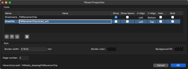
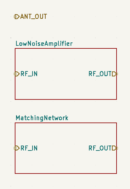
In this example, we’ve connected an LED, a resistor, and a battery. However, you’ll be working on a much larger project for this course that has more components, connections, signals, and other fun stuff. Placing all of these elements in the same sheet can get really messy! It can also make it harder to debug your PCB later. To avoid this, we can use multi-sheet designs to separate components into modules and show how modules connect to one another.
If your design is looking large, but you can separate it into independent modules that do not connect to one another, you can make a flat design. This is a project that has multiple independent sheets that are not connected in any way.
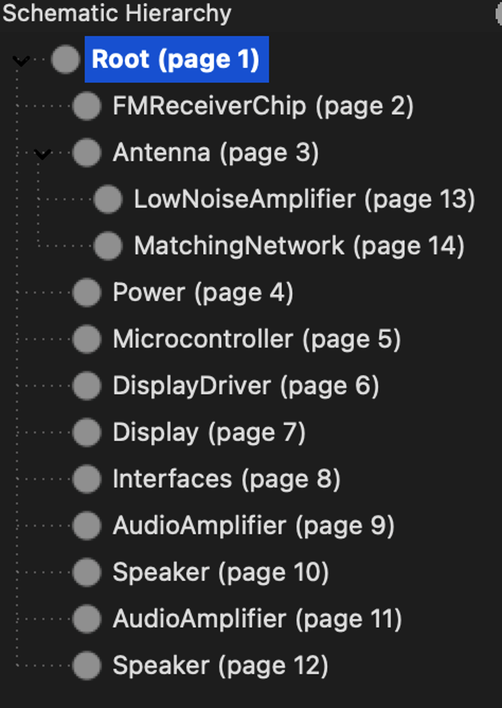
On the other hand, if you can split your design into modules that are interdependent, a hierarchial design can work for your project. This involves multiple sheets with shared signals or connections between modules in each sheet, like a tree with branches off of it. The schematic for your project for the course will likely be a hierarchial design.
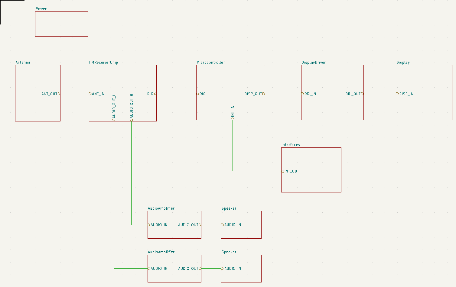
Regardless of whether you choose a flat vs. hierarchial design, you can organize the sheets in your design using a top sheet. This shows what sheets are in your design and how they connect.
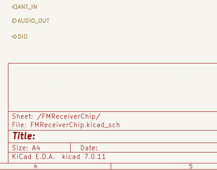
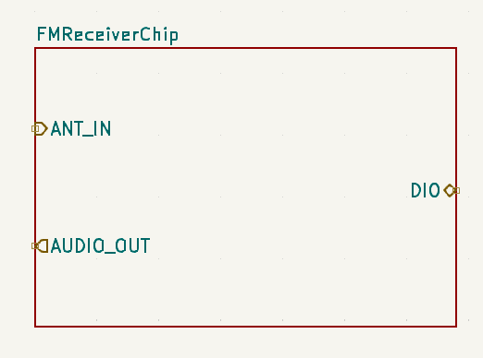
Above is an example of a top sheet, taken from SEVT’s battery management system and included in last year’s class as a case study. Signals that are shared between sheets are represented as Hierarchical labels (Altium calls them ports). These are different from net labels. Net labels have a sheet-only scope. For instance in the U_IO sheet I can make a net called GPIO1 and the net name will actually be U_IO/GPIO1. This means if I make a net label in U_Power called GPIO1, it will be called U_Power/GPIO1. This means they’re not connected, despite both being net labels in seperate sheets.
For more information on how to implement a multi-sheet design, check out this page for KiCAD.
Layout Basics (LSM, Trace Widths, Design Rules)
OK yay, now we need to actually make the PCB itself. Schematic defines the circuit, layout defines the board.
You’ll see a very very blank board. You won’t even see components. That’s because we need to tell KiCAD to import the components from the schematic to the PCB.
Once you exit this menu, you can click and put down your components.
This is hard to demonstrate with 3 components, but KiCAD has some algorithm for placing down components separated by sheets. Here’s what our LED Demo PCB looks like when first imported. You can sort of make out each section just by what’s duplicated. You can also see that if a sheet or a set of components are selected in the schematic, they all get highlighted in the PCB view. This makes it really handy for large PCB project layout. You can also then right click this highlighted group and select “Pack and Move Components (P)” and KiCAD will re-group that highlighted set based on what thinks is a decent layout, and then you can move it anywhere!
Back to the tutorial. Since we only have 3 components, we can drag and rotate them individually until it’s to your liking. You can also use a larger grid for a neater layout. We like to use 1mm or so.
You can also define these layers using File -> Board Setup -> Physical Stackup. The default PCB is a two layer PCB. KiCAD can do basic layer stackups but can’t do certain things like Rigid-Flex and a bunch of fancy math stuff. You can learn about what Altium’s Layer Stack Manager does here but for our class and most things that aren’t a computer or RF, Kicad’s stackup works fine. We’ll also talk about layer stackups later this week.
Calculating Trace Widths + Spacing
All limits in electrical systems are either based on voltage or current. Limits due to voltage depend on the dielectric breakdown between any two points in the circuit (usually $V_{IN}$ and $GND$). If you give a chip a voltage any higher than the specific rating, it will explode immediately and you’ll have to shove all the magic smoke that makes chips work, back into the chip.
And ratings due to current are generally thermal limitations. ALL electrical items have resistance and therefore experience power dissipation at the rate $P_{thermal} = I^2 R_{component}$. If the device heats too much, it can melt or explode which is why components generally come with a “continuous” current rating where the device can release that heat to the surrounding environment just as fast as it’s being generated. And a “burst current” rating where the device can operate at this higher current rating for a certain period of time before the heat build-up is too much.
Trace width is a function of the desired current capacity. The distance between the traces is a function of the required voltage difference between the traces and the dielectric of the material (generally air), or whatever the board fabricator can make. Here’s a good tutorial on that. You’ll also want to space things out if you’re routing sensitive signals and can’t have signal noise from one trace to another. We’ll talk about this more next week, and you won’t have to worry about it much.
For this lab, we are working at low voltages and low currents. We won’t consider distance between the traces this time (in the future we will teach you). But we’ll look at current capacity for argument’s sake. Here’s a good starting table.
There’s a really good tutorial on calculating trace-width for power as well as the impedance of a trace from Millennium Circuits.
Note that the “weight” of the trace refers to the density of copper, higher density copper carries more current. The “thickness” of the trace is set by the “layer thickness” in the physical stackup. You’ll also want to make sure the trace isn’t too thin to manufacture. Generally most PCB fabricators are good with 6 mil traces and larger including PCBWay (which we’re using), but check with your fab. For this lab, you can use the table to select your trace width or go with a standard 10mil trace. 1 mil = 0.001 inch.
Routing the PCB
Routing means connecting things with traces. Traces are like wires. We’ll just use all the default settings. Note that the components default to sitting on the Top Layer of the board, so we can only connect traces to them on the top layer. The exception to this is the JST connector because it’s through-hole, and not surface mount. This means we can connect to it on the top and bottom layer. Internal layers of the PCB (if they existed, they don’t in this case) need to be electrically accessed with VIAs, but that will come in a future lecture.
This tool will allow you to draw traces. You can click to put down a trace or to create a curve– play around with it! Notice the thin grey lines in the layout between the components. These are the nets, they are what you have to connect to each other, and they should match your schematic. The grey border around the trace is a “keepout zone” for the track and it tells you where you can’t have a trace that’s a different connection than the one you’re routing. This sometimes shows up depending on your settings and if you set stuff right. Let us know if this doesn’t show up for you.
Defining Board Shape (Mechanical Layers)
Finally, you may have noticed that the board is comically large for the components on it. So let’s define a shape.