Disclaimer: This guide is NOT an endorsement of any of the companies or entities that we're listing. All expressed facts and opinions are those from the instructors (Winnie and Will) and do NOT represent MIT, the PCB class, or any other group we are part of.
Second disclaimer: I (Winnie) have a conflict of interest with Infineon. As of writing this resource in December 2023, I have not received any monetary or technical support from Infineon outside of their datasheets that are freely available on the Internet. They likely don't know I'm even writing this. All expressed opinions and preferences are from my own research and experience outside of Infineon and were established before I developed connections with them.
Resistors
- Choose a package size. What’s the total power budget of the resistor? $ P = I^2 \cdot R $ or $ P = \frac{V^2}{R}$ is your friend. This will help us choose a package. We suggest you de-rate this value a bit (for instance, if your power budget is 0.5W, get a 0.6W + resistor)
| Resistor Package (Imperial) | Power Dissipation | Relative Size |
|---|---|---|
| 0201 | 0.05W | Good luck seeing it, nevertheless trying to solder it |
| 0402 | 0.063W | Barely visible, Barely hand-solderable with lots of practice |
| 0603 | 0.1W | Small but can be soldered by hand and an iron with practice. Good size for hand-placing and reflowing a board. This size and larger often comes with marks that indicate resistance |
| 0805 | 0.125W | A reasonable size, many people start out learning to solder with 0805s |
| 1206 | 0.25W | Pretty big, pretty easy to solder by hand |
We suggest you also look at a physical chart for resistor sizes, as we can’t give you a real-life resistor through the screens (at least, not yet). If you’re in the class you should have a PCB ruler that also shows you package sizes.
-
Calculate your total error budget. If it’s a generic pull-up/pull-down, 5% resistors are likely okay. Typical voltage dividers for voltage measurements use 1%, though high-precision applications may want tighter tolerances. If you’re doing high-precision stuff, you may want to check out this white paper on resistance changes due to temperature rise. One way to combat this is to select a larger resistor package, as they tend to heat up less for the same power dissipation.
-
Resistors are not found in continuous spectrums. If you tried to look for a 50 $\Omega$ resistor for instance, there aren’t that many. This is because resistors are sorted into discrete values. You can check this resource for a full list of different resistor series. If you’re using an assembly service for your board, they might also have a limited set of resistors. Winnie has a Resistor Divider Calculator for selecting resistors in a resistor divider that are in JLCPCB’s standard library.
Capacitors
Be aware, capacitors are also made in discrete sizes, similar to resistors. They come in even fewer bins. A few common sizes are:
- 100
- 220
- 330
- 470
- 560
- 620
- 750
- 820
- 1000
Multiply by your favorite factor of 10.
I’ll be honest, I was going to write some stuff. But Altium’s guide on capacitors is pretty good. Yes, it applies to KiCad users too. Here’s a brief summary of how to choose a capacitor type:
Aluminum Electrolytic
- High voltage (100V+) energy storage “Bulk Capacitance”
- Low Cost
Hybrid or Solid Polymer Electrolytic
- Medium voltage (<100V) energy storage “Bulk Capacitance”
- Low ESR
- No electrolyte leakage (Solid Polymer only)
Multilayer Ceramic Capacitors (MLCC)
- Medium voltage filtering (<100V)
- Bypassing
- AC Coupling
- Low ESR
- Small size (NOT the same as high energy density)
- MLCC Non-Linearities
- Temperature Rise
- AC bias
- DC bias
- Ripple current
- Looking at it too hard
Film Capacitors
- Low parasitics
- High voltage filtering
- Low leakage current
Inductors
Three specs:
- Inductance
- RMS current
- Peak current
When a large current is run through a current, its inductance decreases. It’s like when water is turning a turbine. Once there’s a certain amount of water being pumped through, you can’t physically cram more water in there. The inductor also has a limit as to how much energy can be stored in its magnetic field. This energy is specifically is stored by aligning the magnetic dipoles (think: tiny compasses) in the core to the current. Once the magnetic dipoles are aligned, they can no longer be more aligned, and can’t store more energy. The energy stored in an inductor is $U = \frac{1}{2} \cdot L \cdot I^2$. If the inductor experiences more current than its current saturation limit, then the inductance increases in order to store the same amount of energy. For this reason, manufacturers rate inductors with a “saturation current”. Different manufacturers have a different definition on exactly when is saturation, but a common definition may be the current where there’s a 30% loss in inductance. Typically, you want the peak current in the inductor to not exceed the saturation current. This is NOT the average current! It’s usually the RMS current + 1/2 * ripple current, since the majority of use cases for inductors use sinusoidal current waveforms.
There’s also a second current rating for inductors, confusing enough. In addition to magnetic limits, there’s also thermal limits. The wires that wrap around an inductor have resistance, and they heat up. With high frequencies, you’ll also have something called core loss, where the magnetic dipoles within the core need energy to change directions faster, and the core will get warm as a result. Typically inductors will express the current limit as the “rated current”, “heat-rated current”, or any variation of these named. This would be the RMS current (not peak current) that would cause the inductor to change by a temperature specification, sometimes defined as $30 ^\circ C$.
If you want to learn more about this, take power electronics (6.131 old, 6.2222 new as of 2024, who knows what EECS will change it to be in 3 years).
MOSFETs
Winnie prefers searching for MOSFETs from AOSMD or Diodes Inc. Both have better search tools than Digi-key, though be aware that not all parts may be in stock.
See Lecture 1’s appendix for a more in-depth explanation on MOSFETs.
- Consider your application and choose the appropriate configuration. Don’t confuse P channel and N channel mosfets. N-channel mosfets are cheaper and have better specs, but they are more difficult to drive for a high-side switching application. Dual MOSFETs are handy if you’re making a half-bridge (synchronous buck converters, most motor drives) but they may not always be the cheapest or most optimal.
- Self explanatory, only use mosfets in production.
- Sort by $V_{DSS}$. You should aim for a value at least 20% higher than the maximum drain-source voltage the fet will experience.
- Sort by $I_D$. You’ll want a value that’s a fair bit larger than the maximum drain-source current the component will experience. The number is a marketing term, so don’t expect to get 50A through a mosfet rated for 50A $I_D$ unless you have a few extra tanks of liquid nitrogen.
- See what voltage you’re driving the gate at. If you’re using a mosfet driver, make sure you sort by mosfets that can withstand that gate voltage.
- Sort $V_{GS_{TH}}$ Max to be lower than your gate drive voltage.
- Calculate the maximum ${R_{DS_{ON}}}$ value you’d like to have based on the power dissipation limit you set. Note that ${R_{DS_{ON}}}$ varies by the gate drive voltage, so choose one that’s closest to it. The power dissipation that’s allowable depends on the package. We provide a general summary here, but be sure to consult the datasheet afterwards:
| Package | Thermal limits (30 $^\circ$ C temperature rise) | Junction-Ambient Thermal Resistance($\frac{^\circ C}{W}$) |
|---|---|---|
| SOT-23 | 0.2W | 150 |
| SOIC-8/DFN | 0.4W | 75 |
| SOIC-8/DFN (EP) | 0.6W | 50 |
| TO-220 | 0.6W | 50 |
If you want a higher thermal limit, you could use a heatsink or use a special top-facing thermal package. Check out this resource for more information.
-
If you’re switching, sort by $Q_G$. The appendix at lecture 1 shows how $Q_G$ relates to thermal losses. Try not to have $Q_G$ be large enough that it causes a significant amount (~70% or more) of total thermal loss.
-
You should have a short list of choices left. We suggest that you go through again and make sure your part fits all the specifications you laid out. One thing to check specifically if you’re using the mosfet as a switch is which regime the mosfet would operate at. You’ll want to make sure the mosfet has a low ${R_{DS_{ON}}}$. Some datasheets provide a ${R_{DS_{ON}}}$ vs $V_{GS}$ chart which make that easy to identify. For this MOSFET, I’d be happy to drive it directly using a 5V microcontroller, but maybe not for a 3.3V microcontroller.

Others may not provide that. Instead, you can look at the $I_D$ vs $V_{DS}$ plot. At the gate voltage that you’re driving the mosfet, the curve should remain in the Ohmic Regime (the plot is linear) for the $I_D$ you’re driving it at. For this MOSFET for instance, if I wanted to use a 3.3V microcontroller to turn on a 5A load, I’d maybe reconsider as it seems fairly marginal.

Op-Amps
When choosing op-amps, you’ll need a few specs to select one:
- Gain Bandwidth Product
- Input voltage range
- Output voltage range
- Slew Rate
First, let’s talk about frequency range. Op-amps don’t magically stop working at a specific frequency. Rather, the gain of the op-amp decreases as frequency goes up. Because of this, we don’t typically describe the op-amp’s “frequency range”. Rather, we talk about its gain bandwidth product. Let’s breakdown what that means. Gain (or more specifically, open loop gain, when the output and input aren’t connected to each other) would be the amplification from the input to the output. Bandwidth would be the frequency that the op-amp is being tested at. If we were to say the gain bandwidth product of an op-amp is 1 MHz (quite low!) then injecting a 1 MHz signal results in a open loop gain of 1 at that frequency. If we were to instead inject a 0.5 MHz signal, then the open loop gain of the op-amp would be 2. Hence, the gain x frequency remains the same, which is why we describe a gain bandwidth product.

In this LM324 Datasheet they show how they test the gain vs frequency with a test signal. The left hand side shows gain in dB. You can convert from dB to absolute using this formula: $G_{abs} = 10^{\frac{G_{dB}}{20}}$. You may also notice that the graph is flat at ~ 110dB around 1 Hz. This is because op-amps have a maximum gain, often referred to as the DC gain. This doesn’t mean the DC gain is low by any means– 110dB is still a gain of 300,000!
For the scope of this class you can assume that if the gain at a specific frequency is fairly high, say at +60dB, then the op-amp probably would be suitable at that frequency. In more advanced controls classes, you might need to do some fancy frequency analysis and even maybe even come up with ways to counteract this effect to get more performance.
Input voltage range is pretty straight forward. There’s specs for it in the datasheet, but usuaully you’ll want the op-amp input voltages to be between +V and -V. The implication there is you’ll want to find an op-amp that can have a supply rail that goes above (or below, if you’re doing negative voltages) your input voltage. You can exceed it by something like 0.3V, but this isn’t recommended since you’re leaving very little margin. The one exception is high-side current sense amplifiers. They can accept a higher input voltage than its supply voltage.
Output voltage range is a little more complicated. Many cheaper op-amps can’t actually output to the full range of their supply. For instance, the LM324 we just looked at has a “output voltage swing” of $0V$ to ($V^+ - 1.5V$). This means that if we had a LM324 hooked up to a 5V rail, the highest it can output is 3.5V. Not ideal for some circumstances, but it might be okay depending on your application. If you need the full output range, there are “rail to rail” op-amps. As the name suggests, their output can go from one rail (the -V power input or 0V) to the other rail (the +V power input). They’re not perfect, as there is still some loss, but it’s fairly good. Take the MCP6002. The output voltage range is from (Vss + 0.025V) to (VDD - 0.025V). This means there’s only a 25mV loss at most. Much lower than the 1.5V of the LM324!
The slew rate is a measure of how quickly the op-amp can change its output, since real op-amps can’t change their output instantaneously. For the LM324, its slew rate is 0.5 $\frac{V}{uS}$, but only if the load is $1M \Omega$ in parallel with $30pF$, and when going from -10V to 10V. In reality, you’ll likely have more output load than that, and you’ll almost never have such a large change. It’s why in the step response signal shown below, the slew rate (the slope of the green line) is actually a little less than 0.5 $\frac{V}{uS}$. Keep in mind, this graph is very zoomed in. Unless you’re working with 50kHz + square waves, it’s likely fast enough for most things.

Logic ICs
Winnie likes using TI as they have a wide variety of logic ICs.
- For basic logic gates like the 74 series, be sure to check the type of input and output the IC has. Some may be open-drain (or open collector, same concept), some may be push-pull. If you want a fast signal (MHz), generally push-pull will be faster. Open-drain is good if you want to create an OR signal with 2 logic gate outputs (you can’t connect 2 push-pull outputs together!). Open-drain outputs also let you output a lower or higher output voltage. For instance you can have a 74LS14 with 5V VCC where the trigger point is based on 5V logic, but if the output is pulled up to 3.3V, you can get a 3.3V signal output.
- Some ICs like the SN74HC595D also have a 3rd output state, sometimes referred to as high-Z. As the name implies, this state is essentially like there’s no IC there. Be sure to define the circuit when an IC is in high-Z, or stray capacitances may hold it at the previous state.
- Different technologies have different voltage ranges. For instance a TLC555 has an input voltage range of 2-15V, whereas a LM555 has a voltage range of 4.5-16V. They also have various other properties like VIH/VIL that may be different across different technologies.
Connectors
Warning: Winnie’s a sucker for locking connectors.
Consumer Power Connectors
- Half of you are here looking for a barrel jack. The standard size for most plugs is 5.5mm outer diameter, 2.1mm inner pin, center-positive. Check out the PJ-002A or the PJ-037A. They’re alright. Winnie doesn’t like them because they fall out too easily.
- Another common connector is the KPPX/KPJX line from Kycon. They’re good for high-current, locking consumer grade power cables. Finding a power supply with that connector is a bit more rare.
- If you’re doing wall power stuff for some reason, first off all talk to us. Then, search for an IEC C13 receptacle.
Internal Power Connectors
- Screw terminals! The common pitches are 2.54mm, 3.96mm, and 5.08mm. The larger ones have higher current rating and can accept larger wires. There’s also two types of mechanical implementations of the screw terminal: the good kind, and the kind that needs to be thrown in the trash.
The junk ones:
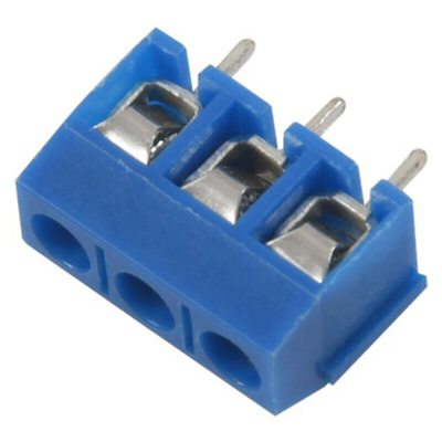
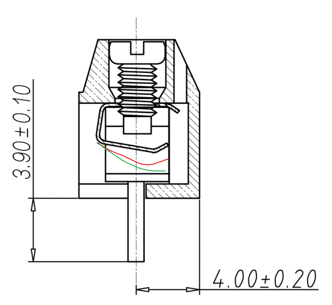
This barely qualifies as a connector because it’s so bad at holding in wires. They’re cheap, but the way they’re so cheap is the screw bends a piece of metal to hold in the wire. The point of contact changes and the wire sometimes shifts away from where it’s being clamped. The clamping force is therefore inconsistent and wires love to come loose. Here’s a cross-section to demonstrate. In red and green are what the metal piece would look like if the screw were to be turned, and as you can see, there would only be a small amount of contact between the wire and the connector.
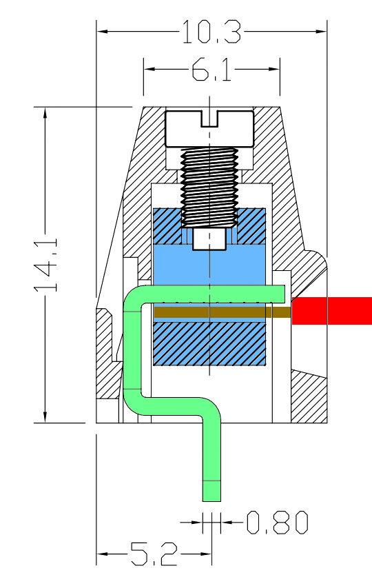
The good ones:
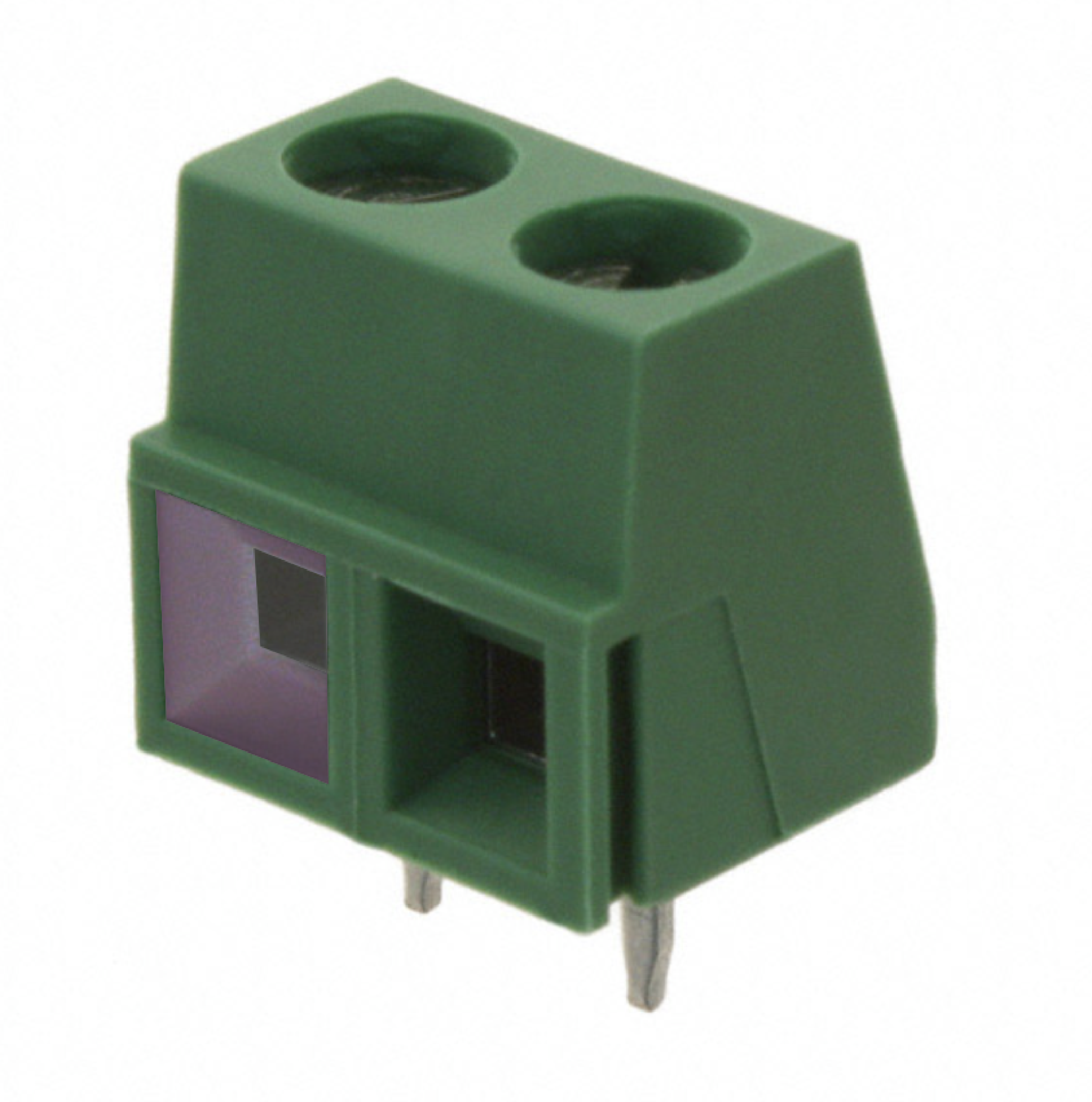
The nice ones typically have a chamfered face leading into the clamp (colored purple) and you can’t see the bent metal piece. Here’a a cross section to demonstrate. The green metal part is soldered down and remains in place. The blue metal part can move up or down by turning the screw. The wire shown is evenly clamped by this type of screw terminal, making a much more secure connection.
-
Molex Mini-Fit are good for high current applications. They can do wire to board, as well as wire to wire. They can conduct 10A + per connector. They’re found very often in computer power supplies and motherboards as they need to transmit ~ 100A of power! As a warning, the Molex naming convention sucks. It’s by far the worst naming scheme for any product that exists and you need to put in extra effort to make sure a connector and recepticle with seemingly random numeric product names mate, but the connector itself is great.
-
JST makes a lot of common internal conenctors. They’re polarized which is great to prevent plugging stuff in backwards. Most are wire to board, but some like the JST-SM are good for wire-wire and are often found in LED lighting strips. Here’s a good guide to JST connectors.
-
barrier terminal blocks are great for high current applications. They use a more generic ring crimp for the wire. You’ll often find these when connecting to wall power applications.
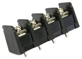
-
The Faston 250 lineup is very common in AC power entry applications. They can connect an AC inlet to a power switch, or to a PCB. The name suggests that the bade width is 0.250 in, but there’s also the Faston 187 or Faston 375.
Consumer Data Cable Connectors
-
USB 2.0 Type C: USB4085. It’s through-hole so it’s much easier to solder than the surface mount USB-C connectors. Note that the lead length is 1.60mm (we think this is to prevent signal reflections in the stub) so the leads may not stick out of your PCB.
-
Micro-USB: We don’t use them often, but be sure to choose one with mechanical integrity, as they often break.
-
Headphone jack: There’s so many choices! A lot of them have different switches inside to detect the presence of a jack, what type of jack it is, etc. The datasheet should give an explanation of what the switches do, but there can be lots of variety. Keep in mind that they also may be pinned differently depending on if you want a microphone jack or not.
FFC Connectors (Flat Flex Cable Connectors)
Please don’t use FFC connectors for this class. If you’re coming back for other stuff:
Check for a lock. FFC connectors without a lock will come loose unless it’s adhered down. Usually they’ll have a latch or something to flip to lock it.
Check which side the contacts are on. Many cables and connectors are single-sided contact, so be sure to check that they match. Double sided cables and connectors are not ideal since they allow for backwards plugging, potentially killing stuff.
Connector drawings usually specify a specific cable. Be sure to check the thickness and pitch to make sure it matches.
They are very hard to hand solder. Small pin pitch + lots of plastic, easy to destroy the connector. Can’t flood it with flux, it can cover the contacts and increase contact resistance.
Board-Board Connectors
Mezzanine connectors are amazing! They take up very little space and often have many pins in the ~ 0.5mm pitch. It’s also the ones that are used in iPhone cables. Be careful of mechanical stresses, as many rigid board-board connections typically feature mounting holes in addition to the connector. Board-board connections are out of scope for this class, but we added them in case you wanted to make some board that’s attached to a flex.
RF Connectors
The type of RF connectors you decide to use are going to primarly be governed by
- frequency range,
- RF performance,
- form factor, and
- mechanical structure
requirements of your PCB.
In terms of form factor, RF connectors typically come as edge mount and vertical mount. Both can involve PTH or SMT, with the former usually being more mechanically secure.
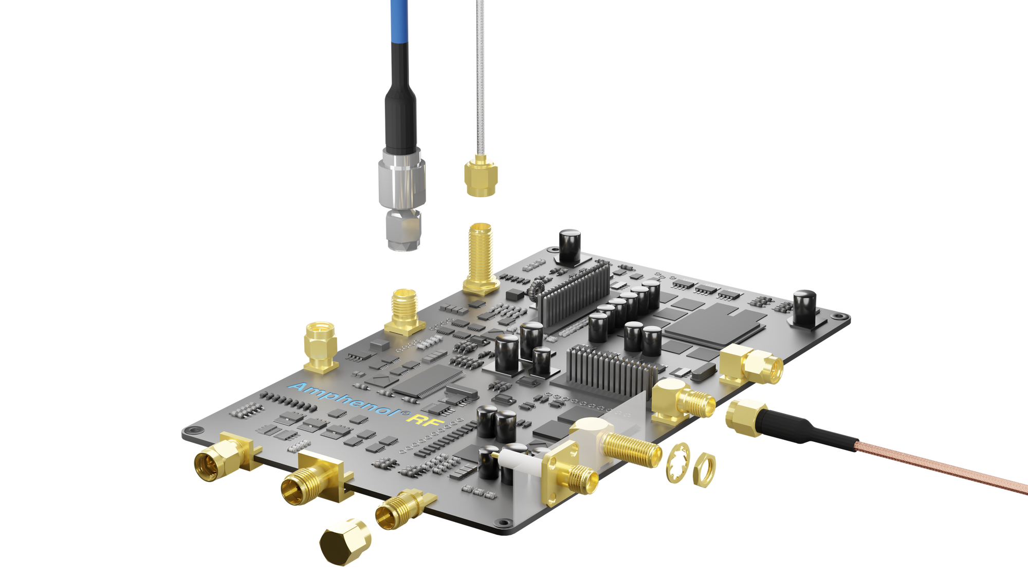 Photo credit: Amphenol RF SMA Connectors Guide
In RF/microwave PCBs used for test and evaluation where connectors do not need to be permanently attached to a board, solderless connectors can be used. These connectors use a special footprint and are screwed into the board. Their center conductor is compressed onto the footprint pad to create a solid connection, which also allows their removal and reuse on other boards.
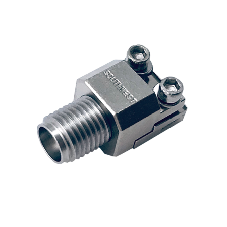
Photo credits: Southwest Microwave
All RF connectors will be built with some sort of impedance match (most commonly 50 ohms), which must match with the rest of your RF devices. Additionally, it is a good idea to take a look at the insertion loss performance in a part’s datasheet to determine if it meets required specifications. When adding an RF connector to a PCB, it is important to follow the manufacturer’s recommended footprint closely in order to maintain proper impedance matches
-
BNC is one of the more common RF connectors and is usually good up to 4 GHz. It’s great for applications where a user will be plugging in and out an RF cable to a board very frequently, which BNC is very easy to do with. However, it is not a great connector for very high frequency applications and it has a very large overall size. Additionally, BNC is prone to having electrical connectivity issues over time.
-
SMA is another very popular RF connector and are capable of up to 14 GHz (depending on the manufacturer). Their threaded nature makes them much more suited for more permanent connections while still allowing ease of removal.
-
U.FL connectors are small surface mount connectors that can be manufactured to support all sorts of frequency ranges. These will be found in embedded devices where there is limited space, and as such these connectors can be very fragile. The U.FL connectors are best used for connecting an external bulkhead connector to a PCB.
-
2.92mm (K) connectors are mechanically similar to SMAs but are designed for very high frequencies, usually 40 GHz and beyond. They are best used for applications involving mmWave frequencies where other connectors would introduce too much loss. While they also are mechanically compatible with SMAs, care should be taken when doing such a mismatch as 2.92mm/K connectors are also much more fragile.
Microcontrollers
Keep in mind, our target audience is people who just took circuits. We know that there's many other microcontrollers. There's TI's MSP430, Cypress' PSOC, the list goes on and on. We're going to focus on the ones we enjoyed working with, and what we found works well for people who want to start learning with a microcontroller that does a little more than what Arduino makes, but don't want an entire new IDE.
ESP32
Winnie loves the ESP32 series. They are Wi-Fi capable microcontroller modules for under $3 each. They even include the antenna in the carrier module so you don’t have to design one, and there’s a lot of community support for them! The newer ESP32-S2 and ESP32-S3 series also feature USB support, so you don’t need a USB to serial converter! They also can be programmed in the Arduino IDE after installing a board library. That being said, some articles online suggest that their ADC quality suffers once Wi-Fi is turned on, and if you don’t need Wi-Fi, other microcontrollers likely have better features for the price.
They also sell the individual IC, but we’ve found that it doesn’t make much sense to re-design the Wi-Fi antenna and stuff unless you’re really into that, or you need every last ounce of space.
STM32
Powerful and low-cost microcontrollers. Also very commonly used by the electronics community, and can also be programmed in Arduino after a library install. They also have a GUI in STM32CubeIDE (ST’s own IDE) to configure different peripherals. One downside is there’s a lot of part names. As of writing this, Digikey sells 3785 different STM32 microcontrollers! This means some microcontrollers in the STM32 family work better than others for Arduino IDE compatibility, and you’ll want to do a Google search to see what’s compatible before designing.
ATTiny
A series from Atmel. They’re very cheap and are small, making them great for simple projects. One drawback is they don’t have much GPIO or processing power. Although, if you’re looking for something cheap and small, that’s the tradeoff. Often times they need an external programming circuit, and lots of people made adapters to program them, or headers to stab into a board to program then remove.
RP2040
We haven’t done much with it, but lots of people have! It’s a very powerful microcontroller, especially given that it sells for $1. Some people have used it to drive DisplayPort Displays (granted it’s at a limited solution) and others have bitbanged Ethernet (also to a questionable degree). It seems like the ceiling is quite high for these microcontrollers.
Modules
In applications that do not have strict space or cost requirements, commercial off-the-shelf microcontroller modules can be used. These integrate the power regulation and interfacing required for a microcontroller in a small board with castellated mounting pins that allow SMT soldering to another PCB. If you’re planning to sell wireless communication based PCBs, modules are also great to work with. They likely already have FCC certification, so you don’t need to go to Uncle Sam to get your circuits approved for RF emissions.
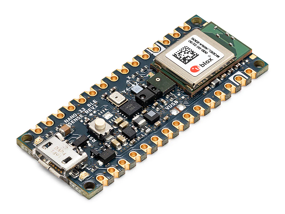 Photo credits: Arduino
Fuses and Fuse holders
-
glass fuses you’re used to seeing in many appliances are 5x20mm fuses. They contain the spark after being blown, so great in areas where you can’t have a spark.
-
Mini blade fuses are great. They’re often used in low-voltage applications where space is a premium. One important note is the fuse is not fully contained– it may spark when blowing, so don’t use it where you can’t have ignition sources.
-
Polyfuses can reset themselves after being blown. They’re not as fast acting as blade fuses, but they can be nice if you’re making a final product with say a motor that tends to draw too much current and you don’t want the user to replace a fuse.
Time delay in fuses
Let’s imagine you’re in the control room for a 1A rated fuse. You see 1A. Do you cut the connection? No. The rating is sometimes called the holding current, meaning the current it can hold until the end of the planet without blowing.
What if you see 1.1A? Surely it’s over the 1A limit, so it should blow. Well… since most fuses are set off by a piece of metal melting, the fuse should blow eventually… though it may be hours if it’s a small excess of the rated current.
Now, let’s say we see 1.5A. Pretty clear it’s in excess of the 1A limit, so the fuse blows in a seconds depending on the fuse type. Fact-acting vs slow-acting fuses will differ in this regime.
Let’s go way over the limit now. If there’s something like 10A flowing through that fuse, that tiny piece of metal will blow in fractions of a second.
Here’s a chart from Littelfuse that illustrates this concept in their mini-blade fuses.
